1. Overview
SDR-B1 is a software defined radio platform based on Xilinx XC7Z045 + ADI AD9363/AD9361 launched by Zencheer Communication. In the hardware design of V1.0 and V1.1, EEPROM storage chips are not supported. Recently, some customers have proposed to add EEPROM to SDR-B1 to store MAC address, serial number and other information. This document gives the complete process of adding EEPROM storage chip based on SDR-B1 V1.1. The EEPROM chip model used in this article is AT24C02.
2. Modify Vivado Project
Most EEPROM storage chips have an I2C interface. In the original SDR-B1 Vivado project, the I2C interface is not brought out, so the Vivado project needs to be modified first.
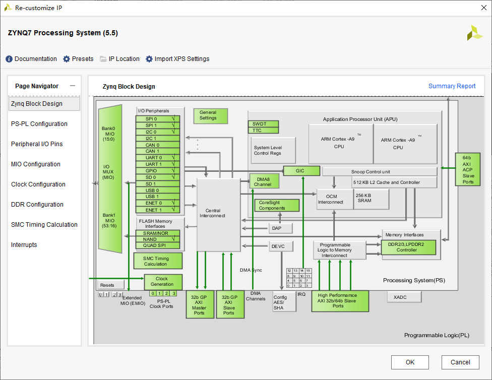
(1) Open the Vivado project of SDR-B1, double-click system.bd in the project file, and then double-click ZYNQ that appears in the right window to enter the Re-customize IP interface, as shown below
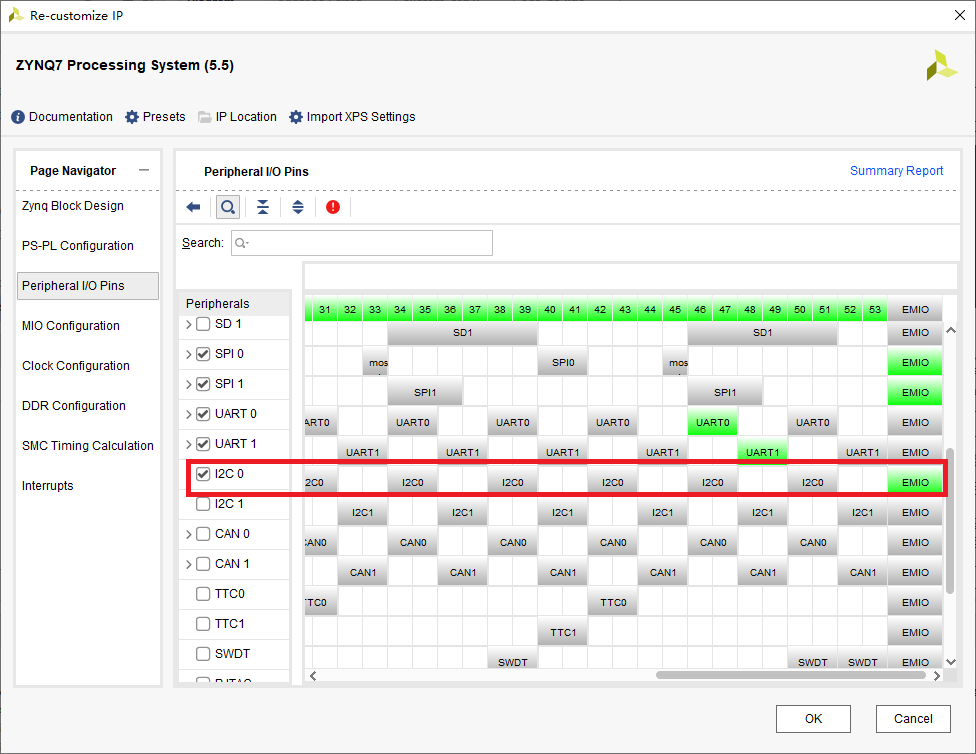
Click Peripheral I/O Pins on the left and check I2C 0 on the right. Since the MIO interface corresponding to I2C 0 is already occupied, Vivado automatically assigns I2C 0 to EMIO, as shown below.
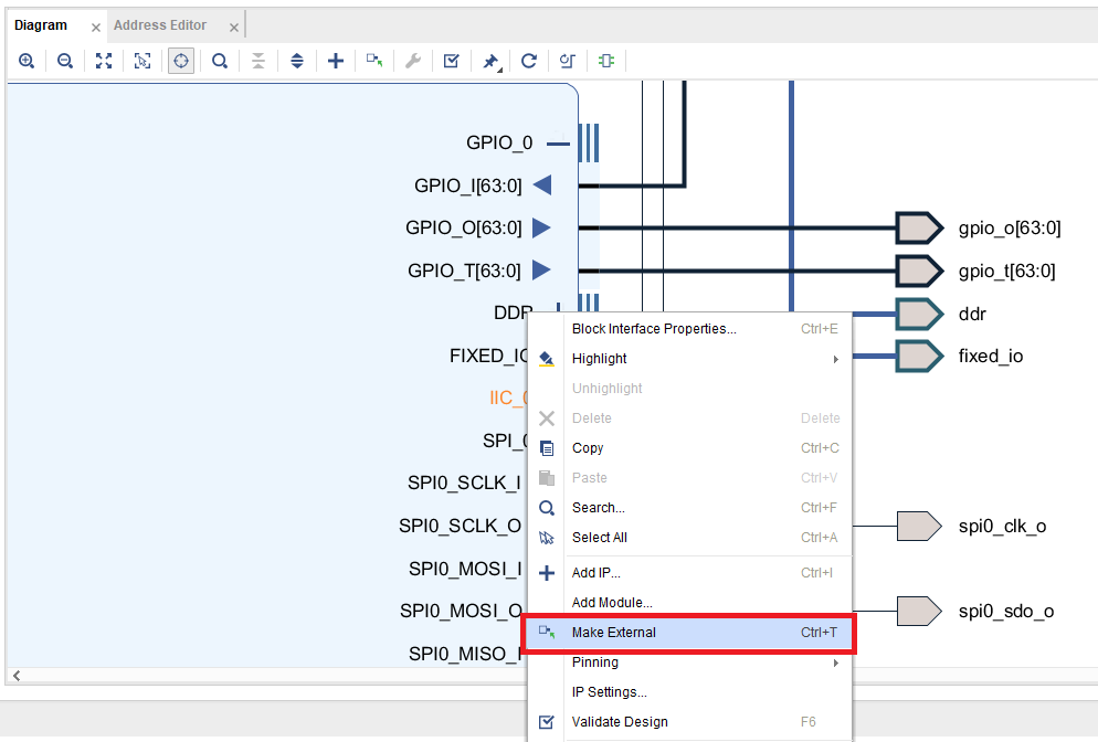
Then click OK and close the Re-customize IP interface. You can see that ZYNQ has an additional I2C 0 interface. Right-click on it --> Make External, as shown below
Then you can Regenerate Layout and Validate Design, and proceed to the next step after confirmation.
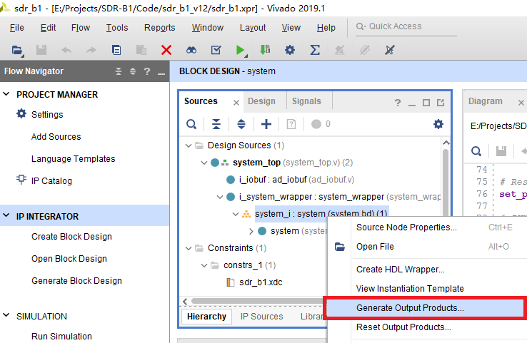
(3) Right-click on system.bd in the source code structure on the left and re-Generate Output Products, as shown below
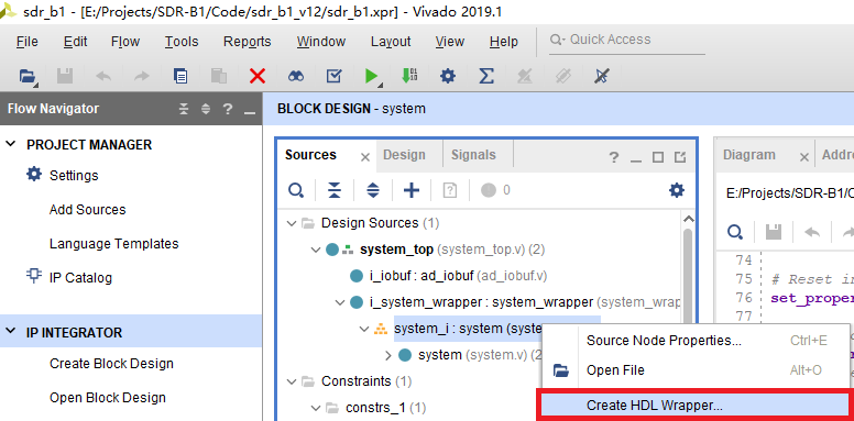
Then re-Create HDL Wrapper, as shown below
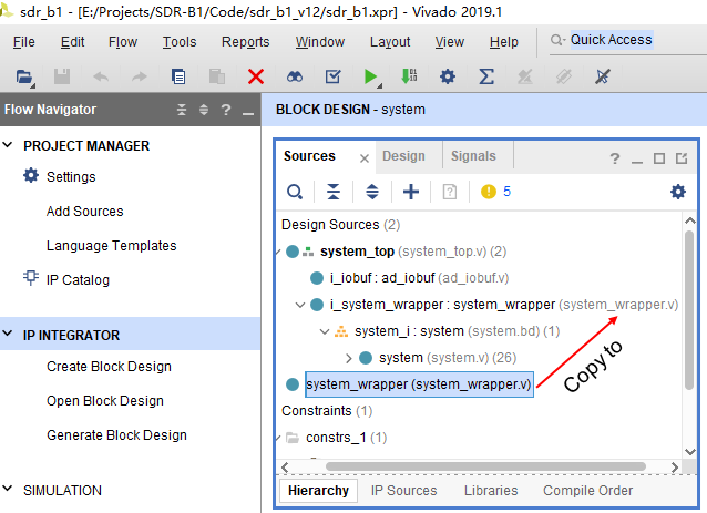
And copy the contents of the newly generated system_wrapper.v to the original system_wrapper.v so that the upper layer can instantiate it, as shown below
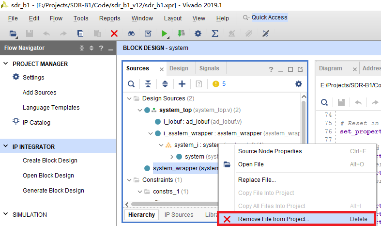
Then delete the newly generated system_wrapper.v from the project, as shown below
(4) Modify system_top.v and add the following two lines in the system_top module:
inout           i2c0_sda,
inout           i2c0_scl,
Modify the system_wrapper instantiation module and add the following two lines:
.IIC_0_0_scl_io(i2c0_scl),
.IIC_0_0_sda_io(i2c0_sda),
Modify sdr_b1.xdc and add the following three lines:
# I2C0 (just for test, pl_gpio_0 as i2c0_sda, pl_gpio_1 as i2c0_scl)
set_property -dict {PACKAGE_PIN AF17    IOSTANDARD LVCMOS33}    [get_ports i2c0_sda]
set_property -dict {PACKAGE_PIN AG16    IOSTANDARD LVCMOS33}    [get_ports i2c0_scl]
That is, PL_GPIO_0 is used as the SDA pin of I2C 0, and PL_GPIO_1 is used as the SCL pin of I2C 0. PL_GPIO_0 and PL_GPIO_1 are selected as SDA and SCL because these two pins already have pull-up resistors, and only the original grounding capacitors need to be removed.
(5) Generate Bitstream in Vivado. After Vivado regenerates the system_top.bit and system_top.hdf files, copy them to Linux for use in the Petalinux project.
3. Modify u-boot
(1) Create a new Petalinux project. The process here is similar to the one in the article "Building the Development Environment for the SDR-B1 Software Radio Platform", but some of the steps can be omitted. Assuming that the system_top.bit and system_top.hdf files have been placed in the /home/lics/data/share/sdr_b1_v12/ directory, enter the following commands in sequence:
cd ~data/code/petalinux/
source /home/lics/data/code/petalinux/settings.sh
petalinux-create --type project --template zynq --name sdr_b1_v12
cd sdr_b1_v12
cp -a /home/lics/data/share/sdr_b1_v12/* .
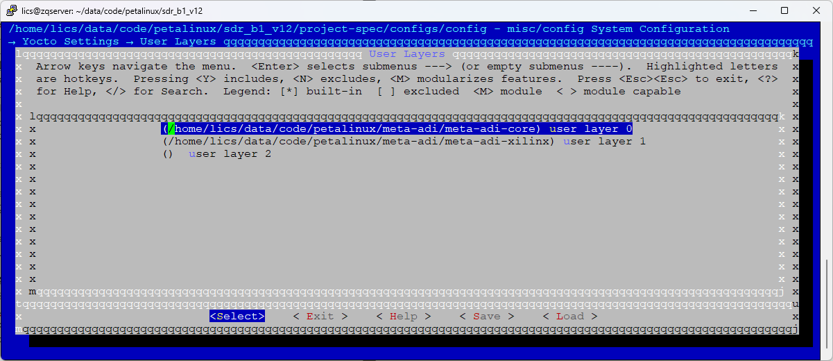
petalinux-config --get-hw-description=/home/lics/data/code/petalinux/sdr_b1_v12Select Yocto Settings on the configuration interface that appears and press Enter. Then select User Layers on the next configuration interface and press Enter. Enter the path of meta-adi-core in user layer 0, which is /home/lics/data/code/petalinux/meta-adi/meta-adi-core, and enter the path of meta-adi-xilinx in user layer 1, which is /home/lics/data/code/petalinux/meta-adi/meta-adi-xilinx, as shown below.
(2) Modify project-spec/meta-user/conf/petalinuxbsp.conf and add the following content:
KERNEL_DTB = "zynq-adrv9361-z7035-bob"

RM_WORK_EXCLUDE += "u-boot-xlnx"
RM_WORK_EXCLUDE += "linux-xlnx"
KERNEL_DTB is used to specify the dtb file, RM_WORK_EXCLUDE is used reserve the source code after compilation (Petalinux will delete the source code after compilation to save disk space).
Use petalinux-build to compile once. This step will take a long time.
(3) After the first compilation is completed, you can find the u-boot source code under build/tmp/work/plnx_zynq7-xilinx-linux-gnueabi/u-boot-xlnx/v2019.01-xilinx-v2019.1+git999-r0/git and copy it out, for example, to components/ext_sources/uboot-source/.
Run petalinux-config, enter Linux Components Selection ---> u-boot (u-boot-xlnx) --->, select ext-local-src,then exit to the last step, enter External u-boot local source settings --->, set it to the directory of the u-boot source code, in this document it is /home/lics/data/code/petalinux/sdr_b1_v12/components/ext_sources/uboot-source/, then save and exit petalinux-config.
To modify the u-boot source code afterwards, you only need to modify the source code in uboot-source.
Enter the sdr_b1_v12/components/ext_sources/uboot-source directory and enter the following command:
cp board/freescale/common/sys_eeprom.c board/xilinx/zynq/
cp board/varisys/common/eeprom.h board/xilinx/zynq/
vi board/xilinx/zynq/sys_eeprom.c
Change
#include "../common/eeprom.h"
if (!env_get(enetvar))
to
#include "eeprom.h"
//if (!env_get(enetvar))
Enter the following command:
vi board/xilinx/zynq/MakefileAdd the following content:
obj-$(CONFIG_ID_EEPROM) += sys_eeprom.oEnter the following command:
vi board/xilinx/zynq/KconfigAdd the following content:
config ID_EEPROM

bool "support ID eeprom"

default y

help

Say Y here to add support for Sample
at Reset Utility. You need this only if
you work on a Marvell development board.
If not, keep this off to reduce code size

config SYS_I2C_EEPROM_CCID

bool "support I2C_EEPROM_ID"

default y

help

Say Y here to add support for Sample
at Reset Utility. You need this only if
you work on a Marvell development board.
If not, keep this off to reduce code size

config SYS_I2C_EEPROM_NXID

bool "support I2C_EEPROM_NXID"

default n

help

Say Y here to add support for Sample
at Reset Utility. You need this only if
you work on a Marvell development board.
If not, keep this off to reduce code size
Go back to the sdr_b1_v12 directory and enter the following command:
vi project-spec/meta-plnx-generated/recipes-bsp/u-boot/configs/config.cfgAdd the following content:
CONFIG_ID_EEPROM=y
CONFIG_SYS_I2C_EEPROM_CCID=y
CONFIG_SPL_I2C_SUPPORT=y
CONFIG_DM_I2C_COMPAT=y
CONFIG_I2C_EEPROM=y
CONFIG_SYS_I2C_EEPROM_ADDR=0x50
CONFIG_SYS_EEPROM_SIZE=256
CONFIG_SYS_EEPROM_PAGE_WRITE_BITS=3
CONFIG_SYS_EEPROM_PAGE_WRITE_DELAY_MS=10
CONFIG_SYS_I2C_EEPROM_ADDR_LEN=1
CONFIG_SYS_I2C_EEPROM_ADDR_OVERFLOW=0x2
CONFIG_SPL_I2C_EEPROM=y
CONFIG_SYS_EEPROM_BUS_NUM=0
Among them, CONFIG_SYS_I2C_EEPROM_ADDR is used to specify the address of the EEPROM chip, which is 0x50 in this article; CONFIG_SYS_I2C_EEPROM_ADDR_LEN is used to set the address length, the address length of AT24C02 is 1 byte, so it is set to 0x1; CONFIG_SYS_EEPROM_BUS_NUM is used to specify the I2C Bus number, which is 0 in this article. At this point, the modification of the u-boot source code has been completed.
4. Modify Linux Code
(1) For the modification of Linux code, this article does not use the same method as u-boot, but adopts the patching method. Enter the following command:
cd ~/data/code
git clone -b 2019_R2 https://github.com/analogdevicesinc/linux.git linux_adi_2019r2
cd linux_adi_2019r2
vi arch/arm/boot/dts/zynq-adrv9361-z7035-bob.dts
Change the axi_i2c0 node to disabled status and add a new i2c0 node as follows
&axi_i2c0 {

status="disabled";

ad7291-bob@2f {
compatible = "adi,ad7291";
reg = <0x2f>;
};

eeprom@50 {
compatible = "at24,24c32";
reg = <0x50>;
};

};

&i2c0 {

status="okay";

eeprom@50 {
compatible = "at24,24c02";
reg = <0x50>;
};

};
Then enter the following command:
git diff > 0001-dts-add-eeprom-for-i2c0-by-zencheer.patch(2) Copy the obtained 0001-dts-add-eeprom-for-i2c0-by-zencheer.patch to sdr_b1_v12/project-spec/meta-user/recipes-kernel/linux/linux-xlnx, and create the linux-xlnx_%.bbappend file in sdr_b1_v12/project-spec/meta-user/recipes-kernel/linux with the following content:
SRC_URI_append += "file://0001-dts-add-eeprom-for-i2c0-by-zencheer.patch"
FILESEXTRAPATHS_prepend := "${THISDIR}/${PN}:"
In this way, you can apply the 0001-dts-add-eeprom-for-i2c0-by-zencheer.patch patch during the Linux compilation process. At this point, the source code modification for Linux has been completed.
5. Verification
(1) Enter the sdr_b1_v12 directory and use petalinux-build to compile again. After the compilation is complete, enter the following commands in sequence:
cd images/linux/
petalinux-package --boot --format BIN --fsbl zynq_fsbl.elf --fpga system.bit --u-boot --force
cd ../..
rm -rf /home/lics/data/share/linux
cp -a images/linux /home/lics/data/share/
At this point, you can copy the compiled BOOT.bin and image.ub to the TF card for testing.
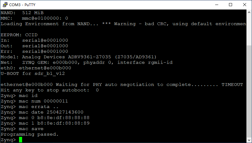
(2) Power on the SDR-B1, press Enter when "Hit any key to stop autoboot:" appears in the serial port, and enter the following commands in sequence:
mac id
mac num 00000011
mac errata ..
mac date 250427143600
mac 0 b8:8e:df:88:88:88
mac 1 b8:8e:df:88:88:89
mac save
When "Programming passed." appears in the serial port, it means that the above information has been written correctly. As shown below
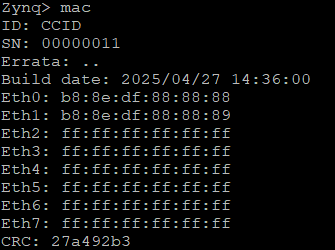
(3) At this time, enter the mac command to display the written MAC address, serial number and other information, as shown below
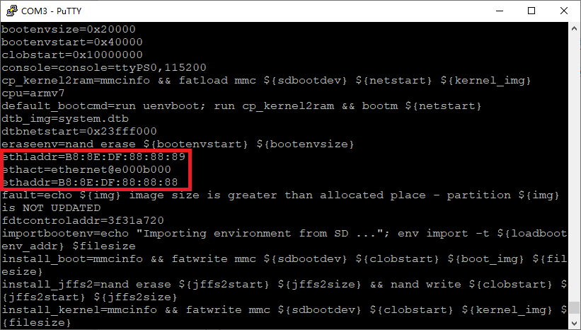
Enter the printenv command, and you can see that ethaddr and ethaddr1 are also correct values, as shown below
(4) Restart the board. After the board is started, enter the username root and password root to enter Linux. Use the ifconfig command to see that the mac address of eth0 is exactly the value written in u-boot before, as shown below
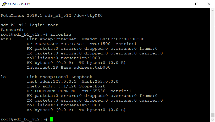
The reason why eth1 is not displayed is that the Linux code is not yet complete. This does not affect the verification result of the EEPROM storage chip.